7-Segment Display CPU Load with Arduino and C#
(Published on November 3, 2014)
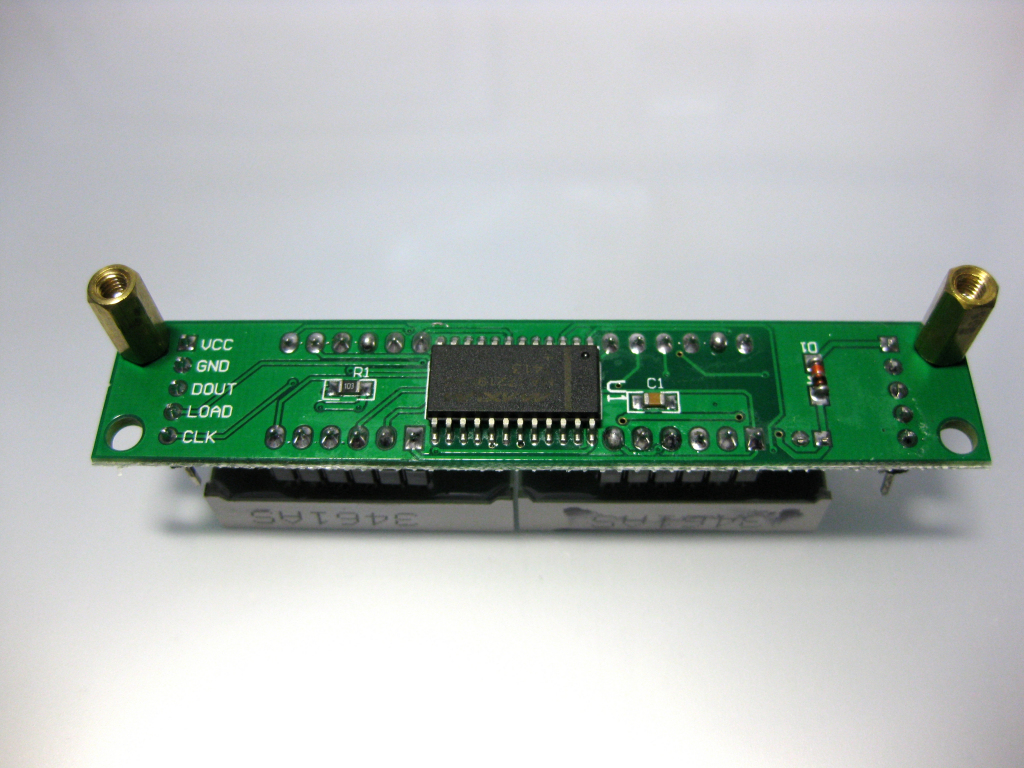
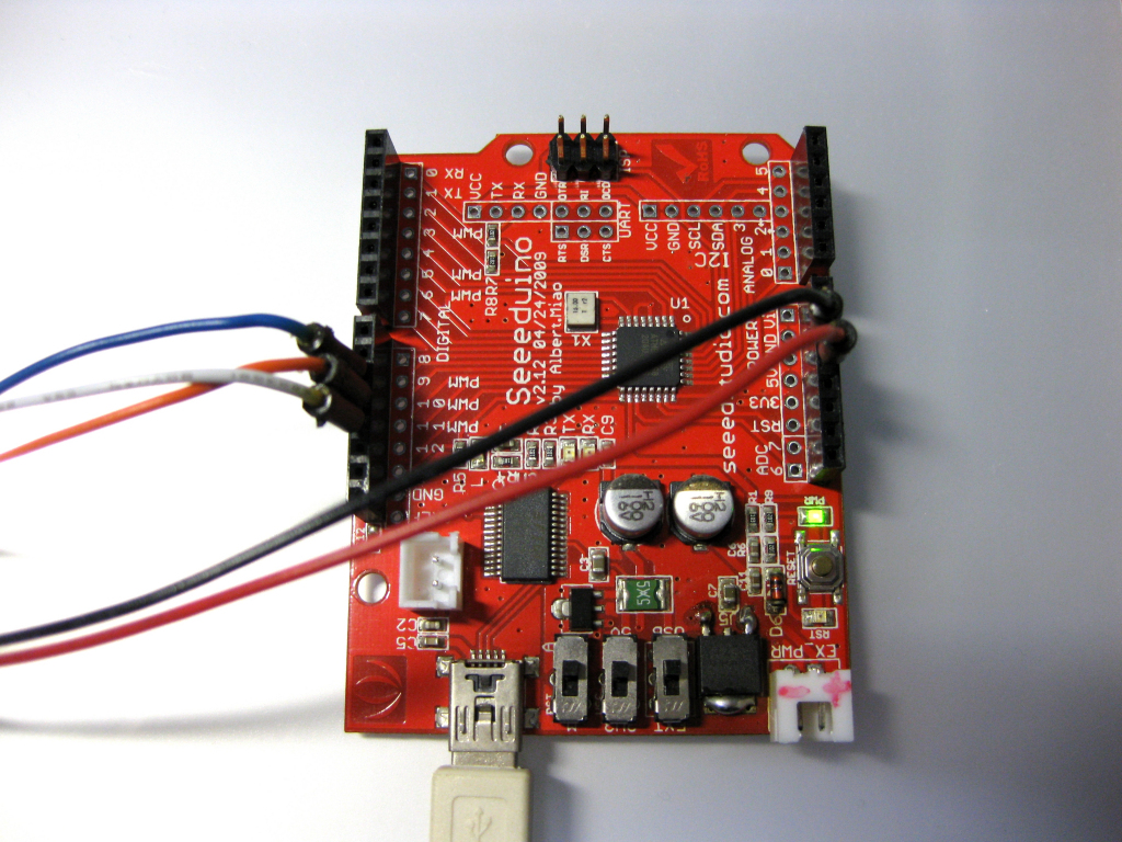
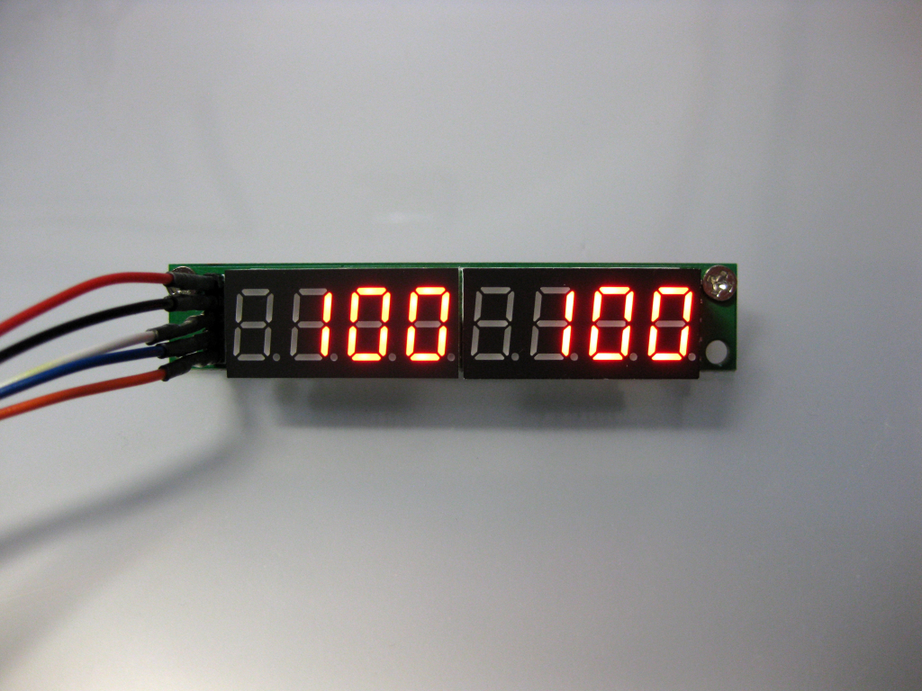
This tutorial will show you how you can use a 7-segment display for showing the Core1 and Core2 load (utilization) of a processor. I used an Arduino compatible board which is called Seeeduino (i'll reference to it as Arduino) and a serially connected 7-segment display capable of showing 8 digits (2x4 digits). The display is connected through the SPI (Serial Peripheral Interface) interface using pins 10,11 and 12 on the Arduino. That 7-segment display can be found on eBay at a low price and is really versatile as a second module can be daisy chained for showing even more data (Core3, Core4, or any other numerical data etc.). The 7-segment display uses a MAX7219 led display IC driver.
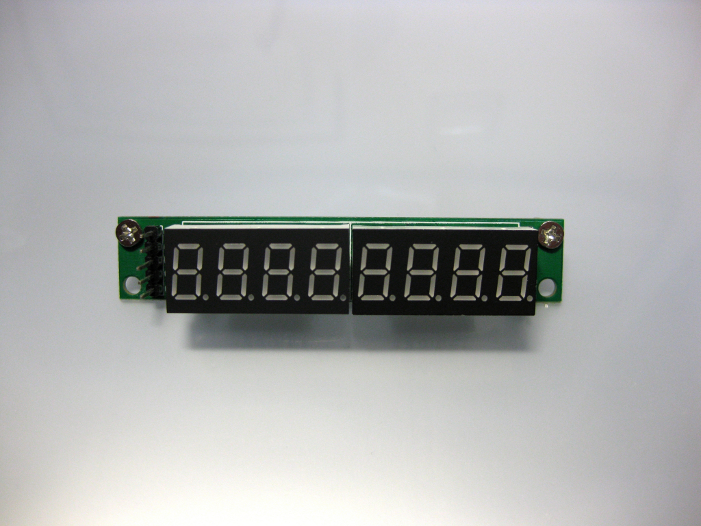
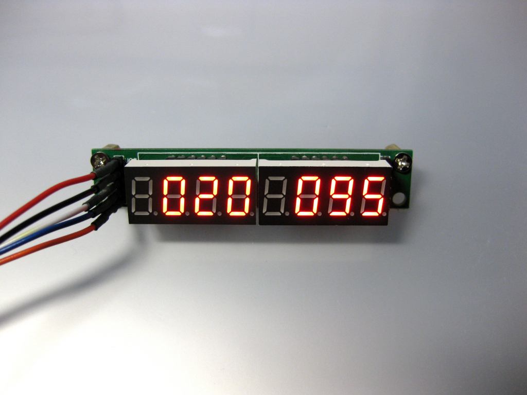
The digits are numbered from right to left like 7 6 5 4 (for the left display) 3 2 1 0 (for the right display). This numbering applies to the Arduino code for showing numbers in the correct order.
Making the required connections:
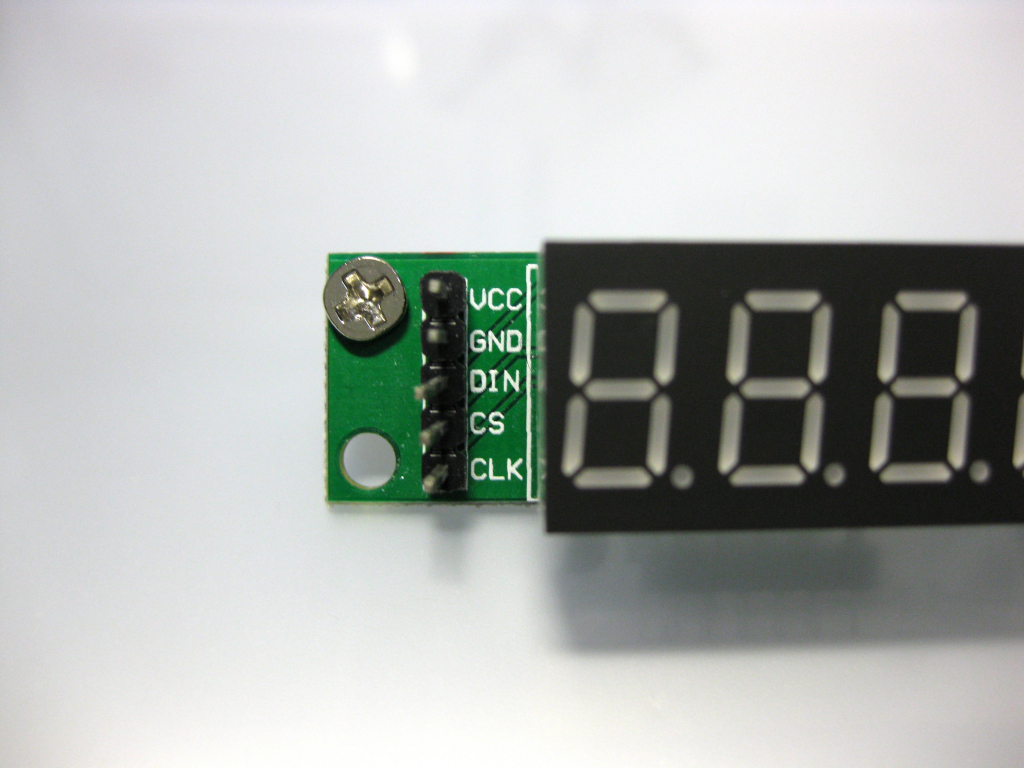
Connecting the 7-segment display to Arduino is a rather simple procedure. Connect the wires as follows:
7-segment display > Arduino
------------------------------------
VCC > 5V
GND > GND
DIN > PIN 12 (MISO)
CS > PIN 10 (SS)
CLK > PIN 11 (MOSI)
7-segment display > Arduino
------------------------------------
VCC > 5V
GND > GND
DIN > PIN 12 (MISO)
CS > PIN 10 (SS)
CLK > PIN 11 (MOSI)
The Arduino code:
Below is the code that runs on Arduino. Copy and paste it into an empty Arduino sketch. You will need the LedControl library to be installed in order to compile and upload the sketch. The LedControl library is responsible for driving the MAX7219 IC and can be downloaded from here. I used version 1.0.6 of the Arduino IDE and 1.0.6 of the LedControl library without any problems.
/*

 This sketch works along with the CPU Load Display application and shows
 Core1 and Core2 load to a 7-segment display that is serially connected
 to Arduino.

 by John Tompros (2014)

 URL to project:
 https://www.blueinteger.eu/index.php/electronics/7-segment-display-cpu-load-c-sharp

 Version 1.0
 Code licensed under Creative Commons Attribution-ShareAlike 3.0 License
 https://creativecommons.org/licenses/by-sa/3.0/

 The connections from the 7-segment display board to Arduino are:

 7-segment display > Arduino
 ---------------------------
 VCC > 5V

 GND > GND

 DIN > PIN 12  (MISO)

 CS > PIN 10   (SS)

 CLK > PIN 11  (MOSI)

 */

#include "LedControl.h"  //Required library

int coreOneLoad;  //Integer to store Core1 load
int coreTwoLoad;  //Integer to store Core2 load

/*
Create the LedControl object, the first three parameters refer to the SPI connections
 and the fourth on how many MAX7219 ICs are connected. One in our case.
 */
LedControl lc=LedControl(12,11,10,1);

void setup()  //Setup routine
{
  Serial.begin(9600);    //Initialize serial port
  lc.shutdown(0,false);  //Wake up the MAX7219 from power-saving mode
  lc.setIntensity(0,8);  //Set 7-segment display led intensity
}

void loop()  //Main program
{
  while (Serial.available() > 0) {  //While the serial port has incoming data do the following

    /*
     Serial.parseInt() returns the first valid (long) integer number from the serial buffer.
     Characters that are not integers (or the minus sign) are skipped.
     Serial.parseInt() is terminated by the first character that is not a digit.
     Serial.parseInt() inherits from the Stream utility class.
     */

    /*
     The following line is the related code from the C# application:
     serialPort1.Write(coreOneData + "\n" + coreTwoData + "\n");
     */

    int coreOneLoad = Serial.parseInt();  //Store the data before the first \n
    int coreTwoLoad = Serial.parseInt();  //And then store the data before the second \n

    //At the second \n which signifies the end of the data that has been sent (in that time period), do the following
    if (Serial.read() == '\n') {

      //Display the Core1 load
      //lc.setDigit(0,7,(byte)thousands(coreOneLoad),false);  //Disable digit 7 as it is not needed
      lc.setDigit(0,6,(byte)hundreds(coreOneLoad),false);
      lc.setDigit(0,5,(byte)tens(coreOneLoad),false);
      lc.setDigit(0,4,(byte)ones(coreOneLoad),false);

      //Display the Core2 load
      //lc.setDigit(0,3,(byte)thousands(coreTwoLoad),false);  //Disable digit 3 as it is not needed
      lc.setDigit(0,2,(byte)hundreds(coreTwoLoad),false);
      lc.setDigit(0,1,(byte)tens(coreTwoLoad),false);
      lc.setDigit(0,0,(byte)ones(coreTwoLoad),false);
    }  //End of if
  }  //End of while
}  //End of main


//Function that returns the ones of a number
int ones(int a){
  int x;
  x = a % 10;
  return x;
}

//Function that returns the tens of a number
int tens(int a){
  int x;
  x = (a / 10)%10;
  return x;
}

//Function that returns the hundreds of a number
int hundreds(int a){
  int x;
  x = (a / 100)%10;
  return x;
}

//Function that returns the thousands of a number
int thousands(int a){
  int x;
  x = a / 1000;
  return x;
}
What the code does:
Arduino waits for incoming serial data (coming from the C# application) and when data is received it separates the data into two parts (using the "parseInt()" function of the Serial class). The first part corresponds to Core1 load and the second part to Core2 load. Also, it has four functions for returning the ones, tens, hundreds and thousands of the parsed data. This processing is needed in order to display the core load in each digit of the 7-segment display.
Testing the code and the hardware:
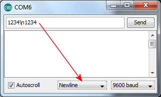
In order to test the code open the serial monitor of the Arduino IDE and enter 1234\n1234, select Newline from the drop down list and click send. As you can see, the first \n is included as well as the second \n (from the drop down list).
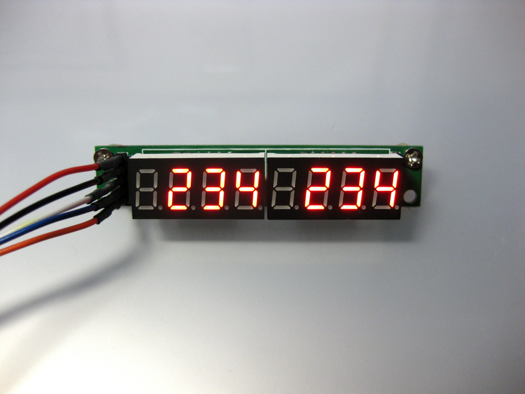
Your 7-segment display should show 234 and 234 (only 3 digits are displayed in each segment as we have disabled digits 3 and 7 in the Arduino code).
The C# application:
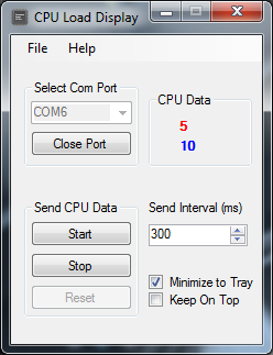
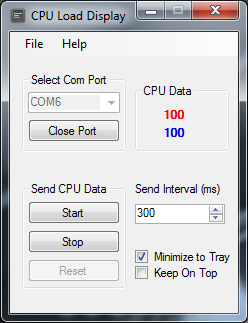
Now that the Arduino code is working as expected let's create the C# application. We are going to create a C# Windows Forms application using Visual Studio. I used VS 2010 Pro but i believe Visual Studio Express 2013 for Windows Desktop can also be used as well, although i haven't tested this myself. The screenshot below shows the completed application. { Icon credit goes to Fatcow Web Hosting }.
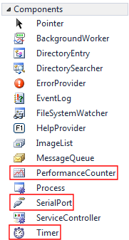
This application uses various controls such as buttons, labels etc. but the most important are the serial port, the two performance counters and the timer components. The following two screenshots shows the mentioned components.

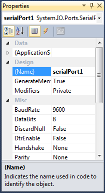
In the Properties section of serialPort1 (screenshot below), the BaudRate, DataBits, Parity and other common settings are kept at their default values so there is no need to set or change them.
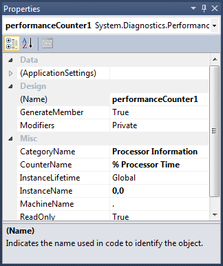
In the Properties section of performaceCounter1 (screenshot below) you need to select CategoryName as "Processor Information", CounterName as "% Processor Time" and InstanceName as "0,0". This represents Core1.
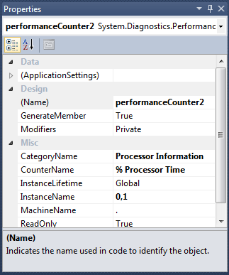
For performaceCounter2 (screenshot below) you need to select also CategoryName as "Processor Information", CounterName as "% Processor Time" and InstanceName as "0,1" this time. This represents Core2.
The C# code:
Below is the full C# code. I have used only one main form named "form1" and an "About Box". In order to compile and run the code you need to have placed the related controls and components on form1. As an exercise, you could study the code and then create the project on your own. The project's name must be "CPU Load Display". You can download the executable here.
/*
 * This application sends Core1 and Core2 load data to an Arduino and this data is displayed
 * to an SPI connected 7-segment display.
 *
 * by John Tompros (2014)
 *
 * URL to project:
 * https://www.blueinteger.eu/index.php/electronics/7-segment-display-cpu-load-c-sharp
 *
 * Code licensed under Creative Commons Attribution-ShareAlike 3.0 License
 * https://creativecommons.org/licenses/by-sa/3.0/
 *
*/

using System;
using System.Collections.Generic;
using System.ComponentModel;
using System.Data;
using System.Drawing;
using System.Linq;
using System.Text;
using System.Windows.Forms;
using System.Threading;

namespace CPU_Load_Display
{
    public partial class Form1 : Form
    {
        string[] getSerialPorts = System.IO.Ports.SerialPort.GetPortNames();    //String array to store serial port names
        double coreOneData; //Double for storing performance counter data for core1
        double coreTwoData; //Double for storing performance counter data for core2

        public Form1()
        {
            InitializeComponent();

            //Get serial port names and place them in comboBox
            foreach (string name in getSerialPorts)
            {
                comboBox1.Items.Add(name);
                comboBox1.SelectedIndex = 0;
            }
        }

        //Menu exit command
        private void exitToolStripMenuItem_Click(object sender, EventArgs e)
        {
            //On exit of the application do the following
            if(serialPort1.IsOpen){
                resetBoard();
                System.Threading.Thread.Sleep(100); //Wait a bit
                serialPort1.Close();
            }
            System.Environment.Exit(1); //Exit program
        }

        //Form load
        private void Form1_Load(object sender, EventArgs e)
        {

        }

        //Open/close port button
        private void button1_Click(object sender, EventArgs e)
        {
            try //For error handling
            {
                //If serial port is not open
                if (!serialPort1.IsOpen)
                {
                    serialPort1.Open(); //Open serial port
                    button1.Text = "Close Port";
                    comboBox1.Enabled = false;
                }
                else //Else if it is open
                {
                    resetBoard();
                    System.Threading.Thread.Sleep(100);
                    serialPort1.Close();    //Close serial port
                    button1.Text = "Open Port";
                    comboBox1.Enabled = true;
                }
            }
            catch (Exception)   //If serial port is used by another program do the following
            {
                MessageBox.Show("Check if com port is used by another program and try again.",
                    "Can not open com port",
                    MessageBoxButtons.OK,
                    MessageBoxIcon.Exclamation,
                    MessageBoxDefaultButton.Button1);
                }
        }

        //Combobox
        private void comboBox1_SelectedIndexChanged(object sender, EventArgs e)
        {
            //Select a serial port from the combobox and assign it to the serial port object
            serialPort1.PortName = comboBox1.Items[comboBox1.SelectedIndex].ToString();
        }

        //Menu about command
        private void aboutToolStripMenuItem_Click(object sender, EventArgs e)
        {
            //Show about window
            using (AboutBox1 box = new AboutBox1())
            {
                box.ShowDialog(this);
            }
        }

        //These statements get executed on each timer tick
        private void timer1_Tick(object sender, EventArgs e)
        {
            coreOneData = performanceCounter1.NextValue();  //Store raw performance counter core1 load value
            coreTwoData = performanceCounter2.NextValue();  //Store raw performance counter core2 load value

            coreOneData = Math.Truncate(coreOneData);   //Truncate raw data for core1 load
            coreTwoData = Math.Truncate(coreTwoData);   //Truncate raw data for core2 load

            label2.Text = Convert.ToString(coreOneData);  //Display core1 load to label core1
            label3.Text = Convert.ToString(coreTwoData);  //Display core2 load to label core2

            //If serial port is open
            if(serialPort1.IsOpen){
                serialPort1.Write(coreOneData + "\n" + coreTwoData + "\n"); //Send core1 and core2 formatted data to arduino
            }
        }

        //Code for keeping window on top
        private void checkBox1_CheckedChanged(object sender, EventArgs e)
        {
            if (checkBox1.Checked == true)
            {
                TopMost = true;
            }
            else
            {
                TopMost = false;
            }
        }

        //Start timer button
        private void button2_Click(object sender, EventArgs e)
        {
            timer1.Enabled = true;
            button4.Enabled = false;
        }

        //Stop timer button
        private void button3_Click(object sender, EventArgs e)
        {
            timer1.Enabled = false;
            button4.Enabled = true;
        }

        //Reset arduino board
        private void button4_Click(object sender, EventArgs e)
        {
            resetBoard();
        }

        //Function for resetting arduino board
        private void resetBoard()
        {
            serialPort1.DtrEnable = true;
            serialPort1.DtrEnable = false;
        }

        //Code for minimizing the window to system tray, window resize event
        private void Form1_Resize(object sender, EventArgs e)
        {
            //If the window got minimized and the checkbox2 is checked
            if (WindowState == FormWindowState.Minimized & checkBox2.Checked == true)
                {
                Hide(); //Hide the program from taskbar
                notifyIcon1.Visible = true;
                }
         }

        //Code to restore window on single mouse click on the application's system tray icon
        private void notifyIcon1_MouseClick(object sender, MouseEventArgs e)
        {
            Show(); //Show the program on taskbar
            WindowState = FormWindowState.Normal;   //Set window to normal state
            notifyIcon1.Visible = false;
        }

        //Code that gets executed every time the value of the numericUpDown control is changed
        private void numericUpDown1_ValueChanged(object sender, EventArgs e)
        {
            //Change timer interval, thus how often core1 and core2 load data is send to arduino
            timer1.Interval = Convert.ToInt32(numericUpDown1.Value);
        }
    }
}
Running the program:
When the program is executed, the user is presented with a simple interface for sending Core1 and Core2 load data to the Arduino board. The sending interval timing (timer1.Interval property) can also be altered from 300ms to 3000ms in 50ms increments. Also, the Reset button resets the Arduino board thus clearing the 7-segment display. Below are two screenshots that show 100% load on each core by using Prime95.
And finally, here is a video that shows the project in action during video playback, this time with blue 7-segment displays: